

Perch Lake Lumber CO. Layout Rebuild
Electrical and Control Systems of The Perch Lake Lumber Co. Layout
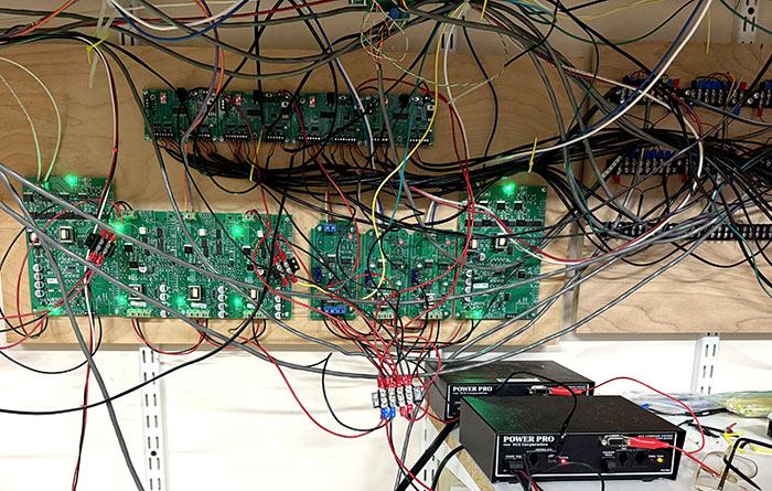
The accompanying photograph illustrates the boards responsible for distributing DCC power and managing turnout operations. Centrally located, from left to right, are an auto reverser for the left block, six circuit breakers—each dedicated to a separate block—and a reverser circuit for the right-side reverse block. Positioned above these components are four turnout control boards, each capable of managing eight turnouts. The first booster supplies power to the two leftmost boards, while the second booster powers the two on the right. Evenly distributing power to boosters for turnouts and blocks ensures balanced DCC current.
Booster wires attach to the lower board terminals, while current-monitored outputs run from the upper connectors through 12-gauge wire to the assigned blocks. BD20 boards located under each block monitor the flow of current and return data to the signal system.
Each turnout controller's eight outputs connect to pins one and eight on matching barrier strips. Twenty barrier strips, each holding eight pairs of terminals, positioned alongside the main power board to align with turnout motor pins numbered one to eight. Only the first and eighth pins operate the motor movement. Pins two, three, and four, as well as five, six, and seven, constitute SPDT switches within the motor assembly. Pins 2 and 3 provide rail power at the turnout's point end. Pin four supplies power to the frog, whereas pins 5, 6, and 7 carry information about turnout orientation to the signaling system.
Continued in Section 8, (Click here)
Return to the start(Click here)
Return to Paul's Workshop (Click here)
Join us in the “Greatest Hobby” as a member of the TLMRC.